Hacking a Mitsubishi Heat Pump / Air Conditioner
Quite a few years back I decided that I wanted to hack my heat pump. The infrared remote control was boring, who wants to press buttons. I thought about automatically generating the infrared remote button protocol like a few others have done before but that still doesn’t tell me what the heat pump is doing. Did it actually turn on after you sent those commands? I thought I could do better, so I decided to pull apart my newly installed heat pump unit and start poking around in there with a meter to see what happened.
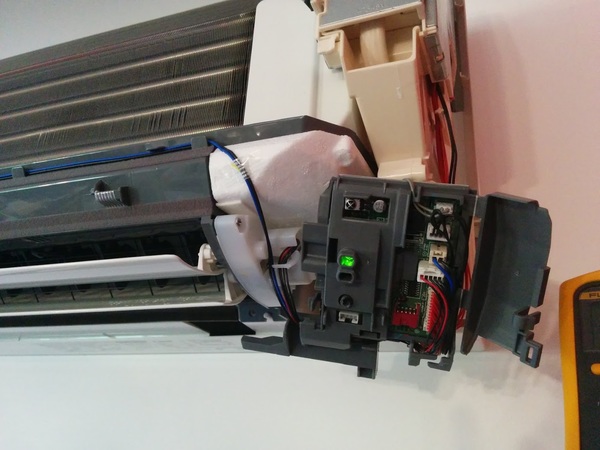
Surprisingly, I remembered to take a couple of photos this time Here’s the unit after pulling off the cover and poking around to find where all the wires were going. Try not to die if you do this with the power on – there’s 240V in there.
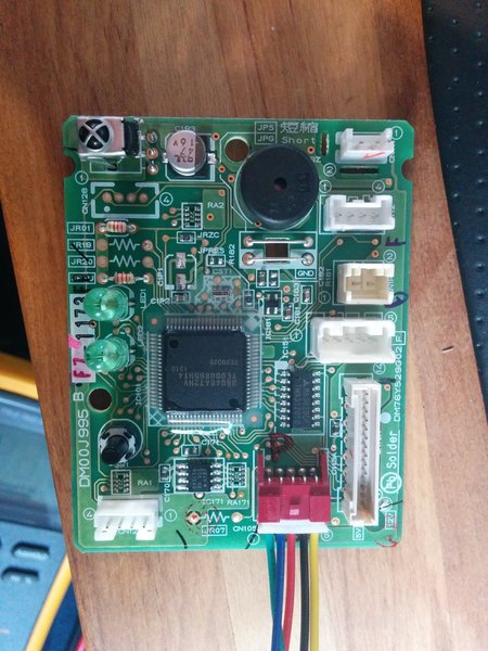
Here I’ve pulled out the control board. Tiny little thing isn’t it! You’ll see one of the wiring looms connected here, this is what we need to connect to communicate with the unit from the outside world – thoughtfully of them they made us a serial port to talk to, it’s 5V TTL UART running at 2400 bps and even parity. A little weird, I discovered that with a Saleae Logic Analyser – a very handy little hacking tool. The connector is called CN105 on the Mitsubishi board.
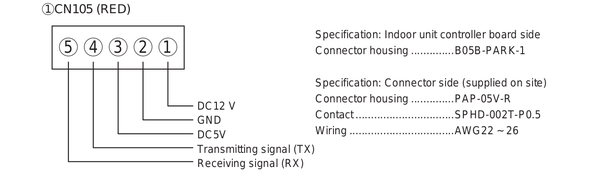
After I had manually poked about and figured out the CN105 pin output and discovered it was a UART, I found this picture of the pinout of the Mitsubishi CN105 connector! Would have been nice to have earlier! Posted here in case you’re building your own cable. The original cable I built was actually a JST PH connector that I carved and sanded to fit in the existing PCB end – figuring out what type of connector was on the board was one of the most annoying parts of the whole thing! I’ve since discovered (after extensive searching!) that it’s a JST PA series and I do have a few cable pigtails here so if you want one drop me a line.
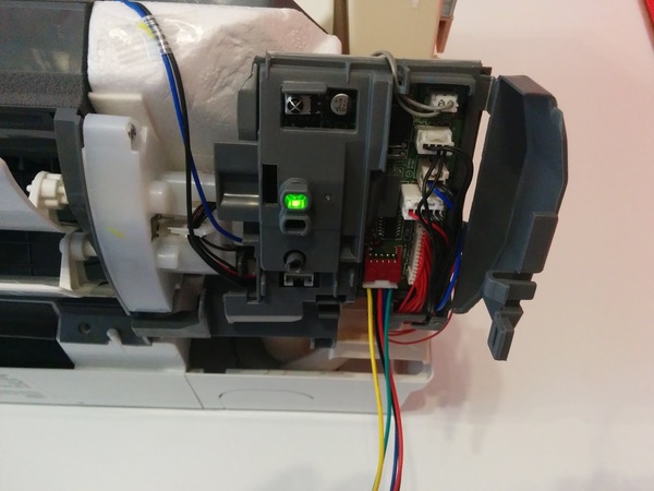
At this stage I’m putting the control board assembly back into the heat pump and connecting it back up to all the factory wiring looms. Once of those is the internal temperature sensor with I did some testing on sensor as part of trying to decode the communications protocol – I think I’ll go into the protocol in a separate post to keep this from getting too long.
Once I got the air conditioning unit back together it was time to implement the hack in a reusable manner. I decided to base my modification on a Raspberry Pi. I could have gone with something smaller such as an Arduino, or an ESP8266 board but I decided to go with the Pi as it would give the ability to relatively easily build a completely stand alone controller for people who don’t have an existing home automation controller to interface with.
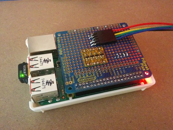
Above is the simple Raspberry Pi break out board mounted on a Raspberry Pi. The couple I have running (one in the office and one at home) are both running on a Raspberry Pi 2 as this was all done before the release of the Pi 3 with built in WiFi. It should work on the Pi 3 okay but I’ve not tested it as yet and there is a change in the Pi UART due to the on board Bluetooth. I guess it should still be able to handle 2400 bps okay but if you test it out let me know!
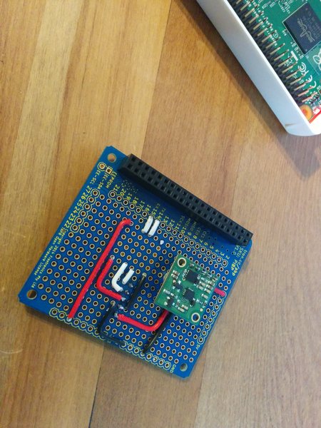
This is just the bottom of the prototype board with some hook up wiring and a 12V to 5V converter from Pololu to power the Pi. The heat pump has a 12V output on the CN105 connector so there’s no external power needed for the Raspberry Pi. There’s also a 5V supply on the connector but I wasn’t sure how much I could draw from that so I decided it was safer to use the 12V rail.
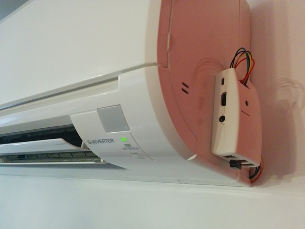
Here’s the final prototype that’s running in my office. The wiring isn’t the tidiest but that’s probably inconsequential when you look at the rest of the office most of the time! I won’t include a photo of that.
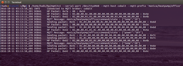
This is the console output from the program which bridges the Mitsubishi Air Conditioner / Heat Pump to an MQTT broker. The code is up on Github here, there’s not a lot of documentation but you should be able to get something working from it.
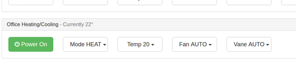
This is a simple control interface in HTML using MQTT over websockets, we use this in house as part of a larger system. I haven’t had a chance to extract this bit of code yet.
Update, as usual I forgot to mention a bunch of things : This is true bi-directional communication with the heat pump, meaning that you can send it commands and get back a response on whether they succeeded. The heat pump will also send unsolicited updates when things change such as using the IR remote. This means that the network interface will always be in sync with what the air conditioner unit is actually doing, no guesswork.
There’s a bunch of documentation to do on this project which I’ve currently run out of time for – though I do hope to be able to pick it up again soon. The next post I hope to do is on decoding the serial line communication protocol. If you’ve got any questions let me know in the comments.

I am unsure if the UART on CN105 is 3.3v ttl or 5v? I am not using or am familiar with the raspberry pi. I only connected a 5v ttl usb to serial convertor on the receive line as I was unsure of the UART voltage level of the Mitsubishi board.
Does a connect byte array need to be issued to see any data? I can’t quite understand the python github as I am not a programmer only a hack, but from what I can understand it looks like when the Heat pump object is initiated it calls self.start_packet = Packet.build(0x5a, [0xca, 0x01]). Is this required to see any data on the serial stream?
I can confirm your code works with US models. I guess the reason the ESP8266 did not work, is logic level. It accepts 5V, but only sends 3.3V. In the world of TTL 3.3V is still supposed to be a logical 1 for 5V logic, but I guess Mitsu is a bit more sensitive. I don’t have a logic level converter yet, so can’t confirm if my C code works yet. But I did hook up a USB 5V UART and used linux to give it a test drive. I made a few small changes, to work with my version of py-serial, but all in all it works as expected.
Hi Matt,
The UART talks 2400,8,E,1 and yes the connect must be sent in order to get an initial HP feedback. There after the info packets must be periodically sent in order to get updates from the HP. For example, I commented out the part that would send the wanted changes to the HP, only info packets sent. Playing with remote and I get its settings. Turn on the wanted send portion and anything I do with the remote, gets over written 😉 Kiddy lockout is how I look at that LoL.
Also, pay close attention to the pin config of cn105, on our HPs you will see near cn105 a 1 and 5 in a circle, those correspond to pin1 and pin5.
For your USB UART
Pin1 12V (leave disconnected)
Pin2 GND (connect to GND or G, depending on model)
Pin3 5V (leave disconnected)
Pin4 TX (connect to RX)
Pin5 RX (connect to TX)
If either of you want to discuss with me, my E -mail is a l (at) s w i c a g o . c o m remove spaces 😉
Thanks for confirming it works with US models. It should co-exist with the IR remote fine, we occasionally use the remote in the house here and the code doesn’t overwrite what is set from there. You might have changed that in your version.
Hi Matt,
AL answered your question but yes you do need to send the connect and info packets, you can’t send more than one per second or the HP won’t respond to them.
The HP UART is 5V and the Pi is 3.3V so you need a level shifter in between those.
Cheers,
Hadley
Great news my code for Arduino works…just not yet on ESP, but at least the C code on a arduino micro and yun works. the esp8266 either needs pull ups on TX and RX, possible a level shifter and maye also have to do Serial.swap (reverses RX and TX) so that ESP boot message isn’t sent to heat pump.
I have not setup a git yet for this, but I posted working code here
http://www.esp8266.com/viewtopic.php?f=29&t=13207
Regards
-AL
I have created an Arduino library. I added it to my post on esp8266.com
http://www.esp8266.com/viewtopic.php?f=29&t=13207
ToDo: Add the info packet sender, in order to get heat pump responses.
Great work! Thanks for sharing your port. That’s really neat, I was considering coding it originally for an ESP8266 but decided on the Pi as I wanted a change from what I’d been doing and could allow people without an existing home automation solution to build something all-in-one with the Pi.
Cheers,
Hadley
https://github.com/SwiCago/HeatPump.git
As long as you can pass Serial or Serial1 it will work. Boards that do not implement HardwareSerial are not supported.
Cheers
-AL
Cheer
-AL
http://hackaday.com/2017/01/06/air-conditioner-speaks-serial-just-like-everythin…
You can use the pin out image, but it’s not mine, I grabbed it from a manual PDF I found online somewhere.
I have completed the HeatPump class for esp8266, it can now also read values from the heatpump. I can confirm that it works for MSZ-FH and SEZ-KD units.
I also recently added a ReadMe for the git, with circuit diagram.
Cheers
-AL
Greetings from Sweden!
I have a MSZ-SF35VE2 and wanted to try this.
I used a USB to TTL adapter and Hadleys python code. It works nice!
I have ordered an ESP-01, and I will try it once I get it in the mail.
However, this model has an “i-save” mode, which allows you to set the temperature down to 10 C. I want to be able to set this mode, but looking at the code it doesn’t look like it supports that.
Of course I tried to set it from the remote and see what happens, this is what I saw in the debug print outs:
isave 10 degrees, heat, fan auto, vane swing:
HP Packet: 0x62 : 02,00,00,01,01,0f,00,07,00,00,03,94,00,00,00,00 : 0xac
isave 16 degrees, heat, fan auto, vane swing:
HP Packet: 0x62 : 02,00,00,01,01,0f,00,07,00,00,03,a0,00,00,00,00 : 0xa0
heat 16 degrees, heat, fan auto, vane swing:
HP Packet: 0x62 : 02,00,00,01,01,0f,00,07,00,00,03,a0,00,00,00,00 : 0xa0
The only thing that changes, as far as I can see, is the 12th byte.
“94” for 10 degrees, “a0” for 16 degrees.
I tried setting the temperature to 31 C, and it changes to “be”
Do you have any good guesses on this?
I have just hooked up an ESP8266 (the adafruit huzzah version which has an onboard regulator and can take the 5v directly from the CN105 port) to my heatpump – MSZ-GE80VA2.
I used the PAP-05V-S JST PA 5 way connector, and RS components had ready-made 300mm leads (SPHD1-SS5-24300) with the crimp contact already installed, so you just push the wires into the connector housing.
– http://au.rs-online.com/web/p/pcb-connector-housings/4766798/
– http://au.rs-online.com/web/p/serial-cable-assemblies/5128737/
I used AL’s https://github.com/SwiCago/HeatPump.git, and have just tried the HP_cntrl_esp8266 example script. I was able to switch it on and off, so looks like it’s working.
Jakob – I have an i-save button on my remote but I have never used it. I pressed it then, but I was still limited to 16-31 degrees. Is it just a case of pressing iSave and then the +/- temp buttons?
I’m going to use the arduino library and write some code to enable MQTT messages to control the heatpump. I will then try and integrate with home-assistant.io. Will post my results!
Thanks Hadley, AL, and anyone else who has contributed to this – really appreciated.
We just need to figure out a way now to get the remote control to update it’s display when the heatpump settings are changed via the cn105 port 😉
Yes, if I select the i-save mode, pressing the temp minus button, it jumps from 16 to 10.
The manual for my model says:
“Normally, the minimum temperature setting in HEAT mode is 16°C.
However, during i-save operation only, the minimum temperature setting
is 10°C.”
I found the manual for your model and it states the same.
Note that is says in HEAT mode, did you try it in HEAT mode?
Really interested in getting MQTT on the ESP8266, it would fit my use case quite nicely.
Speculating further:
As in my previous post, when set to 10 C, the 12th byte is hex 94, 16 C is a0 and 31 C is be.
In decimal:
94 = 148
a0 = 160
be = 190
Which is roughly the temp in F + 100:
148 – 100 = 48 F = 8.9 C
160 – 100 = 60 F = 15.6 C
190 – 100 = 90 F = 32.2 C
I might be on to something?
Thanks Hadley, AL, kayno and everyone else contributing.
Can you post your diagram please?.
Thanks in advance.
My progress is slow. Whilst I can change settings with AL’s ESP8266 code, I can’t read the status from the heat pump. Nothing is coming back on the serial. Any thoughts AL, others? I have tried Serial.read, and Serial.readString in the main loop() and Serial.available() is returning > 0 but nothing comes back from Serial.read(). All a bit odd, given that if I use AL’s library I can switch it on/off.
upon turning it back on, it didn’t beep, and seems to be fine. now I am paranoid about breaking it!!
but I can not connect directly to the unit, since melcloud is through the cloud. I would like to be able to hack this device or make mine own as you have done. I have the witty cloud esp8266 and I would like to know if I also have to join the vcc of 5V the pins of rest and ch_pd. Thanks !!!!!!!
Thanks
The “operation” LED indicator is flashing a on/off for 0.5secs/0.5secs, which according to the service manual is a serial signal error (page 30 of https://www.mitsubishielectric.com.au/assets/LEG/OBH531E.pdf)
https://www.mitsubishielectric.com.au/assets/LEG/OBH531E.pdf gives a procedure to rectify (page 37) which i am working through. I switched the unit off at the mains isolator, waited 30secs, switched it back on, and then pressed the emergency switch as it says. The operation LED starts the same flashing again, and continues even after the 6 mins mentioned in the manual.
I was starting to get somewhere too – I had AL’s code controlling power/mode/fan/vane over mqtt, but it couldn’t read the current settings. i switched to unreality’s fork (https://github.com/unreality/HeatPump) as they seem to have done extended work on reading the status, but it wasn’t reading the status of the heatpump either. I turned on the heatpump via the remote, and thats when the operation LED started flashing. When i realised it wasn’t working, I disconnected the ESP8266, and started troubleshooting.
If anyone has any ideas to help me? I just need to get the heatpump working again, or else my other half is going to be quite upset. My wallet will be upset too if I have killed the control board… or worse 🙁
in the panic of not being able to get it to switch on, I switched it off at the mains and pulled the cover and control board panel off and removed the CN105 cable (figured at that stage i should, as a repairman would likely be visiting!) and put it all back together. Whilst reassembling, I noted a sticker that also had the troubleshooting codes, and it just said “switch off power and wait 60s” – it did not go into the detail of the service manual, but the service manual didn’t mention “60s”. I went and switched back on the mains isolator (it had been off for several minutes whilst i removed the cable), and when i went back in side and pressed “ON” on the remote, it came to life! no more flashing LED, just lots of cold air.
unfortunately now my wife won’t be happy if I plug the cable back in. 31C, 30C and 36C forecast for the next 3 days, and if there is no air con when it’s that hot because I blew it up… anyone know how much the “Indoor electronic control P.C. board” costs, if were to need replacing? I need to do a cost/benefit analysis before continuing. Is there any risk here in breaking it? Hadley, did you ever have the flashing LED problem?
With witty cloud (esp8266-12) is neccesary ch_pd pin ans rst pin to vcc?
In the Al diagram the resistors are in parallel, with witty cloud (same as huzzah) resistors are in parallel o in line?
Thanks in advance
With witty cloud (esp8266-12) is neccesary ch_pd pin ans rst pin to vcc?
In the Al diagram the resistors are in parallel, with witty cloud (same as huzzah) resistors are in parallel o in line?
Thanks in advance
Yeah I seem to recall having to turn the heat pump off and on again a couple of times while I was poking around in there.
Cheers,
Hadley
– RST – this is the reset pin for the ESP8266, pulled high by default. When pulled down to ground momentarily it will reset the ESP8266 system. This pin is 5V compliant.
– EN (CH_PD) – This is the enable pin for the ESP8266, pulled high by default. When pulled down to ground momentarily it will reset the ESP8266 system. This pin is 3.3V logic only
I connect the 5V and GND from the heatpump to the V+ and GND on the HUZZAH. I also connect the RX and TX from the heatpump to the TX and RX on the HUZZAH. I have 10k resistors from each of these lines to the 5V line.
The HUZZAH RX pin is 5v tolerant (“there is a level shifter on this pin”) however the TX is 3.3V logic – but it seems to be enough to transmit commands to the heatpump as I can control it with the HUZZAH.
I have soldiered on though, and seem to have most things working now. Still a little bit of work to go though!
AL, unreality’s fork of your code has some excellent additions, including the checkForUpdate() function. I have forked unreality’s code and started to make some changes myself, but this has mostly resolved around removing magic numbers and trying to make the code more readable. I have some more ideas to improve it, however I am thinking we could continue that conversation on the esp8266 forum where you posted your code?
I’m also working on my home assistant integration as well, and I will post my config when I am done. So far I have home assistant displaying the current state (via an MQTT broker), which looks like this: http://i.imgur.com/0VYAByU.png
Once I have it working so that I can control it from home assistant, I can start to fully automate things – “switch on the heatpump to HEAT in winter when I am 20 mins away from home and it’s below 20C”, “send me a push notification if i leave the house but leave the heatpump on, and allow me to switch it off or acknowledge that I want to leave it on (or turn it off if i don’t respond)” – all possible now 🙂
thanks everyone!
Jakob A – I am able to get lower temps in iSave mode. I wasn’t able to get Hadley’s code working on my laptop using a USB to serial converter though, so I haven’t been able to look at the packets coming back when iSave mode is used. Your deductions with the -100 and Fahrenheit looks promising though – maybe try some more temperatures to see if it continues to compute?
I might look at adding some more debug code to my ESP8266 arduino sketch to send the received packet data out to a debug MQTT topic. that might allow me to help you.
I would also like to control some of the other functions on my model, like “POWERFUL” mode (possibly just an extra fan mode, but the manual says it’s for heat and cool modes only, and that in this mode the temperature can’t be set), “LONG” (increased fan speed, horizontal vane is full up to “throw” the air longer), and “ECONO COOL” (manual reads: “the manual performs swing operation vertically in various cycles according to the temperature of airflows” – sounds like a circus act!). Would be interesting to see of these are specific bytes for other “operation modes” in the data stream, or if they are just “pre-canned” settings, e.g. LONG is most likely just highest fan speed, highest horizontal vane setting.
Thanks for this blog post, been looking for a description of the protocol for a while 🙂
I found some people who have decoded the protocol the official wifi adapters user (http://www.geekzone.co.nz/forums.asp?topicid=148822&page_no=2 and https://github.com/ncaunt/meldec) and it seems they send XML data that contain the bytecode for the heatpump serial commands.
Perhaps if someone has an official unit they could dump the xml when the horizontal vanes are changed? Might be an easy way of decoding more of the protocol.’),
You’re welcome 🙂
Yeah, if someone sends through the encodings for the horizontal vanes that would be great, I’ll add it to the code.
I’ll get around to finding it one day – the larger unit we have in the house has the feature, the smaller one I developed on in the office doesn’t.
Cheers,
Hadley
Your fork (https://github.com/unreality/HeatPump) was most helpful, thanks!! I will get my fork up on github tonight for you to see – would be great to try and get all the changes back into one library somewhere 🙂
Cheers
Kayne
Thanks for looking into it! Were you able to set anything other than 10 degrees?
I will try with other temps and look at what data I get. The problem is that this heatpump is a one and a half hour drive (one way) away. (Which would make remote control really helpful!) And I have other plans for the two coming weekends.
MQTT debug topic seems like a good idea! Do you have any code to share yet?
Cheers!
Jakob
Just did some testing on this tonight and seems pretty good now. I did seem to get a random temperature change when I initially switched it ON (last temp was 24 so not sure where 31 came from) but that could be an issue in my sketch or homeassistant (HASS) setup.
I will try this weekend.
Thanks.
unreality – good find. I looked at the stuff at https://github.com/ncaunt/meldec
It does indeed look like it sends the serial commands/responses over the net.
There was a sample capture there, I decoded a bit of it and put it here I anyone wants to look:
https://gist.github.com/anonymous/cfd1cd3bed730024daa665b29aa0bdcd
There seems to be more to this protocol. Looking at the XML, there is a groupcode, which seems to be the first byte after the header, and there are many groupcodes used.
Alberto – since you have the real hardware, are you able to capture the traffic? Network traffic and/or the serial comms between the wifi adapter and the heatpump?
Cheers,
Jakob
i tried but i dont know do it.
Regards
I will try kayno code tomorrow.
I think dont’ work because my unit is different group code than yours.
Tomorrow i say you
Regards.
I have tried kayno’s and al’s code with witty cloud to my hp.
don’t work. does nothing.
🙁
How could it work?
Thanks everyone.
How would you figure out the data structure of my heat pump model?
Thanks!!!!
If you haven’t already, I would try AL’s library and the HP_cntrl_esp8266 script. This will give you an “esp8266” ssid to connect to, and then when you try to use your browser you should get forced to a page that allows you to connect to the heatpump and change settings.
Your code would work with mycropyhton?
Wittycloud can load mycropython firmware.
Thanks in advance.
I’ve got it working perfect. The problem was that the heat pump takes 2 minutes to start and the connection packet is sent just as the module esp8266 is turned on. I added a delay of 2 minutes and finally works perfect. Thanks Hadley, al, kayno !!!!!!!. The only thing is that when I turn on the heat pump with mqtt it lights up with 28th, otherwise everything works perfect. So the code of headley, al, kayno works perfect in unit pead rp100 ja (European model)
Kayno has can you solved the problem of 28ºC when start heat mode?
Thanks in advance!!!!!
Alberto, I commented on your question on esp forum, but see you got it working. Yes the heat pumps have an initialize time. That is why I made sure in my library you can re-send the connect message. By default it does this as soon as it is plugged in, as you do not need to turn power off to plug in. I have tested my GIT code on both ducted and non-ducted units. For ducted, vane settings are ignored, the units are smart enough to ignor what they don’t have. Also, no point in asking the unit what it is, since you the hacker already know that LOL.
Unreality forked from my main branch, right before I updated the entire package to read from heatpump, Kanyo forked from unreality, so his won’t have any of the new code I put in my branch either. My read from heatpump is done automatically as part of your main loop hp.sync(), instead of on-demand see my git examples. The values are saved in current_settings and can be pulled with any of the methods that read from it, but getSettings(settings*) will get them all at once.
Alberto, Kanyo, Unreality, Hadley you guys can always email me with any suggestions or questions. I posted my email before, but I’ll post it again
al (at) swicago (dot) com
I do check my email often and will periodically check esp8266.com
Cheers
-AL
So the CN105 port must have a way of telling the heat pump what the “current temperature” is. Has anyone seen this protocol deciphered anywhere (one would probably need to sniff what the MIFH1 is sending over the CN105 port). I would like to build something similar to the MHK1 where I have an ESP8266 plugged into the heat pump and another one somewhere else with a temperature sensor on it, and that becomes the remote thermostat.
So the CN105 port must have a way of telling the heat pump what the “current temperature” is. Has anyone seen this protocol deciphered anywhere (one would probably need to sniff what the MIFH1 is sending over the CN105 port). I would like to build something similar to the MHK1 where I have an ESP8266 plugged into the heat pump and another one somewhere else with a temperature sensor on it, and that becomes the remote thermostat.
Alternatively you could just use a separate temperature sensor and adjust the set point of the heat pump if the reading doesn’t match what you’re aiming for.
If I were to make a remote themostat, I would use two ESP8266. One on the cn105 port and the other by the conventional thermostat. When a convention themostat demands heat or cool, it trigers internal relays. Normally you supply 24V to those on common and the thermostat returns the 24V one or more of it’s outputs. You could very well just GND as common and pullups on your input. When the thermostat triggers a relay, it will pull that output to GND(esp input). Depending on mode you know you need to either cool or heat and what fan speed is wanted.
Now on the cn105 ESP, I would just set heat to max temp and turn on/off when thermostat requests heat. On cooling mode, set temperature to min and trun on/off when themostat requests heat. If you don’t want to use 2 ESPs, then you could wire one ESP to your conventional thermostat and tx/rx to cn105 port. Let me know if that makes sense. Otherwise, when I find time I could draw up a schamatic
You can have temperature sensors anywhere in the house, publishing on the MQTT broker.
Then you have a logic system, be it off the shelf like Home Assistant or openHAB etc., or, like we do here, custom control software that makes choices for the heat pump settings based on the input from the separate temperature sensors.
The reason I chose to implement the original system on a Raspberry Pi was for people that don’t have or want to set up a separate home automation system, the Raspberry Pi connected to the heat pump can talk to the heat pump, be the MQTT broker, and do the control logic all in one device.
I think I figured out the temperature values.
I seems like it is temperature in 0.5 degrees C plus an offset of 128 (presumably to allow negative temperatures without using negative values)
10 C = 0x94 = 148 = 128 + 10 * 2
16 C = 0xa0 = 160 = 128 + 16 * 2
31 C = 0xbe = 190 = 128 + 31 * 2
kayno – did you get any data logged when setting temperature < 16 C ?
As I said before, my heatpump is in a remote location and it will be a while before I can go there.
Cheers,
Jakob
http://www.greenbuildingadvisor.com/community/forum/mechanicals/38983/mitsubishi…
They monitored the power consumption and found it was spiking up and down when using the internal temperature sensor, but when they connected the MHK1 the power consumption became much smoother. This leads me to believe that the MHK1 is transmitting the current room temperature to the minisplit and the minisplit is using that temperature, instead of its own temperature sensor.
heatpump/debug/set on // this was me sending “on” to the topic to enable debug mode
heatpump/debug debug mode enabled // confirmation from ESP8266 that debug mode is enabled, packet dumping will commence
heatpump/debug {“packet”:”02 00 00 00 07 09 02 01 00 00 0c ac 00 00 00 00 “} // settings packet with settings, e.g. temp, mode, power, vanes, etc
heatpump/debug {“packet”:”03 00 00 0d 00 00 ae 00 00 00 00 00 00 00 00 00 “} // info packet with room temp
So then i switched mode to HEAT and hit the iSave button:
heatpump/debug {“packet”:”02 00 00 01 01 0f 00 00 00 00 03 94 00 00 00 00 “} // settings packet, after pressing isave and down to 10 degrees C, it now contains the 0x94 you found
heatpump {“power”:”ON”,”mode”:”HEAT”,”temperature”:16,”fan”:”AUTO”,”vane”:”AUTO”,”wideVane”:”|”} // ESP8266 acknowledges the change (reports temp is 16 because it doesn’t know how to interpret isave 10C yet)
heatpump/debug {“packet”:”03 00 00 0b 00 00 aa 00 00 00 00 00 00 00 00 00 “} // info packet with room temp
heatpump/debug {“packet”:”02 00 00 01 01 0f 00 00 00 00 03 94 00 00 00 00 ” // still got that 0x94 in the settings packet…
I think some more debugging is required to suss this out – push a button, check the output, repeat! I might write a script that I can run on my laptop that reads the MQTT debug topic and processes each packet and formats/displays it nicely to assist.
ESP8266/arduino discussion is continuing here: http://www.esp8266.com/viewtopic.php?f=29&t=13207
It will still be a while before I can get to my heat pump and test things. Also waiting for some more electronics to arrive (come on China post!)
I noticed something in your info packets: could the 7th byte could be the temperature in according to my previous theory?
First one: ae = decimal 174 -> 174 – 128 = 46 -> 46 / 2 = 23 degrees C
Second one: aa = decimal 170 -> 170 – 128 = 42 -> 42 / 2 = 21 degrees C
Does it make sense?
Also: the first packet has ‘ac’, was the heat pump set to 22 C?
Thanks again!
Jakob
We have been making strides with the library for ESP. For a few of us, depening on temperature set from remote, the ESP cannot figure it out as it differs slightly your codes.
I got a little bored today and hooked up my Oscilloscope and dumped the Serial packets the official KUMO cloud device sends to the heatpump
Here is what KUMO CLOUD sends for each mode
FC,42,01,30,10,02,00,00,00,00,00,00,00,00,00,00,00,00,00,00,00,7B =>INFO
FC,42,01,30,10,03,00,00,00,00,00,00,00,00,00,00,00,00,00,00,00,7A =>INFO_TEMP
FC,42,01,30,10,04,00,00,00,00,00,00,00,00,00,00,00,00,00,00,00,79 => ???
FC,42,01,30,10,09,00,00,00,00,00,00,00,00,00,00,00,00,00,00,00,74 => ???
TP=Type,pw=power,md=mode,fs=fanSpeed,vv=vane,tF=temp
FC,42,01,30,10,- -,TP,00,pw,md,00,fs,vv,00,00,00,00,00,00,tF,00,CHK
FC,41,01,30,10,01,07,00,01,02,00,00,00,00,00,00,00,00,00,A8,00,CB => DRY
FC,41,01,30,10,01,03,00,01,07,00,00,00,00,00,00,00,00,00,80,00,F2 => FAN
FC,41,01,30,10,01,07,00,01,01,00,00,00,00,00,00,00,00,00,A8,00,CC => HEAT
FC,41,01,30,10,01,07,00,01,03,00,00,00,00,00,00,00,00,00,A8,00,CA =>COOL
FC,41,01,30,10,01,05,00,00,00,00,00,00,00,00,00,00,00,00,A8,00,D0 => OFF
FC,41,01,30,10,01,08,00,00,00,00,01,00,00,00,00,00,00,00,80,00,F4 =>FANQuiet
FC,41,01,30,10,01,08,00,00,00,00,02,00,00,00,00,00,00,00,80,00,F3 =>FAN1
FC,41,01,30,10,01,08,00,00,00,00,03,00,00,00,00,00,00,00,80,00,F2 =>FAN2
FC,41,01,30,10,01,08,00,00,00,00,05,00,00,00,00,00,00,00,80,00,F0 =>FAN3
FC,41,01,30,10,01,08,00,00,00,00,06,00,00,00,00,00,00,00,80,00,EF =>FAN4
FC,41,01,30,10,01,08,00,00,00,00,00,00,00,00,00,00,00,00,80,00,F5 =>FANAuto
FC,41,01,30,10,01,10,00,00,00,00,00,00,00,00,00,00,00,00,80,00,ED => VANEAuto
FC,41,01,30,10,01,10,00,00,00,00,00,01,00,00,00,00,00,00,80,00,EC => VANE1
FC,41,01,30,10,01,10,00,00,00,00,00,02,00,00,00,00,00,00,80,00,EB => VANE2
FC,41,01,30,10,01,10,00,00,00,00,00,03,00,00,00,00,00,00,80,00,EB => VANE3
FC,41,01,30,10,01,10,00,00,00,00,00,04,00,00,00,00,00,00,80,00,E9 => VANE4
FC,41,01,30,10,01,10,00,00,00,00,00,05,00,00,00,00,00,00,80,00,E8 => VANE5
FC,41,01,30,10,01,10,00,00,00,00,00,07,00,00,00,00,00,00,80,00,E6 => VANE_Swing
COMBO settings
HH,HH,HH,HH,HH,mp,MO,00,PW,MO,00,FS,VV,00,00,00,00,00,00,TT,00,CHK
INFO : FC,42,01,30,10,02,00,00,00,00,00,00,00,00,00,00,00,00,00,00,00,7B
INFO : FC,42,01,30,10,03,00,00,00,00,00,00,00,00,00,00,00,00,00,00,00,7A
???? : FC,42,01,30,10,04,00,00,00,00,00,00,00,00,00,00,00,00,00,00,00,79
???? : FC,42,01,30,10,09,00,00,00,00,00,00,00,00,00,00,00,00,00,00,00,74
DRY : FC,41,01,30,10,01,07,00,01,02,00,00,00,00,00,00,00,00,00,A8,00,CB DRY ON
FC,41,01,30,10,01,0C,00,00,00,00,01,00,00,00,00,00,00,00,BE,00,B2 DRY, FAN_Q,88°
FC,41,01,30,10,01,0C,00,00,00,00,02,00,00,00,00,00,00,00,BE,00,B1 DRY, FAN_1,88°
FC,41,01,30,10,01,14,00,00,00,00,00,00,00,00,00,00,00,00,BE,00,AB DARY,VANEA,88°
FC,41,01,30,10,01,14,00,00,00,00,00,01,00,00,00,00,00,00,BE,00,AA COOL, VANE1,88°
FAN : FC,41,01,30,10,01,03,00,01,07,00,00,00,00,00,00,00,00,00,80,00,F2 FAN ON
FC,41,01,30,10,01,08,00,00,00,00,01,00,00,00,00,00,00,00,80,00,F4 FAN, FAN_Q,NO_temp_setting
FC,41,01,30,10,01,08,00,00,00,00,02,00,00,00,00,00,00,00,80,00,F3 FAN, FAN_1,NO_temp_setting
FC,41,01,30,10,01,10,00,00,00,00,00,00,00,00,00,00,00,00,80,00,ED FAN, VANEA,NO_temp_setting
FC,41,01,30,10,01,10,00,00,00,00,00,01,00,00,00,00,00,00,80,00,EC FAN, VANE1,NO_temp_setting
HEAT : FC,41,01,30,10,01,07,00,01,01,00,00,00,00,00,00,00,00,00,A8,00,CC HEAT ON
: FC,41,01,30,10,01,0C,00,00,00,00,01,00,00,00,00,00,00,00,94,00,DC HEAT,FAN_Q,50°
FC,41,01,30,10,01,0C,00,00,00,00,01,00,00,00,00,00,00,00,BE,00,B2 HEAT,FAN_Q,88°
FC,41,01,30,10,01,14,00,00,00,00,00,00,00,00,00,00,00,00,94,00,D5 HEAT,VANEA,50°
FC,41,01,30,10,01,14,00,00,00,00,00,01,00,00,00,00,00,00,94,00,D4 HEAT,VANE1,50
COOL : FC,41,01,30,10,01,07,00,01,03,00,00,00,00,00,00,00,00,00,A8,00,CA COOL ON
FC,41,01,30,10,01,0C,00,00,00,00,01,00,00,00,00,00,00,00,A0,00,D0 COOL, FAN_Q,61°
FC,41,01,30,10,01,0C,00,00,00,00,02,00,00,00,00,00,00,00,A0,00,CF COOL, FAN 1,61°
FC,41,01,30,10,01,0C,00,00,00,00,01,00,00,00,00,00,00,00,BE,00,B2 COOL, FAN_Q,88°
FC,41,01,30,10,01,0C,00,00,00,00,02,00,00,00,00,00,00,00,BE,00,B1 COOL, FAN_1,88°
FC,41,01,30,10,01,14,00,00,00,00,00,00,00,00,00,00,00,00,BE,00,AB COOL, VANEA,88°
FC,41,01,30,10,01,14,00,00,00,00,00,01,00,00,00,00,00,00,BE,00,AA COOL, VANE1,88°
Looks like temp can always be sent, with any setting. It looks like there is a magic byte that says what the payload could contain. The above seems pretty easy to replicate and I am sure I could recode a branch of the library to do the above.
I wrote (yet another) Arduino/ESP8266 library, if anyone wants to contribute or check it out at http://github.com/jarrod180/
Also in Australia we call the Air Conditioners …. not sure about you blokes over there with your chilli bins and jandles.
@AL – Look at hadley’s code, the second byte of the tx settings message (after the kind designation of 0x01 for settings), there is a byte containing individual bits set for each setting contained in the message.
I bet you had a great time with the logic analyser figuring this stuff out! Thanks again.
It seems to me that the 6th byte is a bitmap of the values you want to change.
In accordance to my earlier theory, 12th byte is the temp setting in 0.5 degrees C plus an offset of 128. It matches perfectly with your logs. For example A0= decimal 160 -> 16 C = 61 F.
And also where you set FAN mode, the temp value is 80, which is 128, hence 0C. Makes sense, because in fan only mode, it should neither heat or cool, so the temp setting is irrelevant.
Jakob
Nice work on the library looks good (even from you guys with your thongs and stolen Pavlova).
You and Jakob are both correct that there’s a bitmap byte for what settings you’re changing.
Cheers,
Hadley
Cheers
-AL
The current code is only using 0x02 for the set commands plus confirmation and 0x03 for the temperature feedback.
There are several other packets types that I’ve ignored in the code, 0x06 being one of them which appears to be something to do with the external unit, I don’t remember off the top of my head what 0x04 and 0x05 were.
Someone in the thread was wondering what the ECONOCOOL mode does. It sets the target temperature up four degrees (F) from the requested temp and turns on cycling of the vertical vanes. The theory is that having the air blow on you makes you feel cooler so you don’t need to actually cool the room as much. Kind of a silly feature, in my opinion.
I’m not that great with hardware. Can I hire anyone to build me a bunch of these controllers?
I was actually planning on building a little custom board for this purpose at some stage (we have a pick and place here) but I just haven’t had the time yet unfortunately.
I would say that the Adafruit Feather ESP8266 is probably the best option if you’re wanting to go with the ESP8266 route, it is pretty easy to hook up.
Cheers,
Hadley
– huzzah: https://www.adafruit.com/products/2471 (you have to solder headers on to it, and need a USB FTDI cable to program)
– feather: https://www.adafruit.com/products/3046 (headers already soldered in, normal USB cable to program)
Whereabouts in the world are you? I have a couple of spare headers and could whip up some more cables to suit a huzzah/feather…
– the wide vane setting is sent on byte 18 (where first byte is 0)
– the bitmap control byte value for this packet is set in byte 7 (not not 6 as for the other settings) and has a value of 0x01
See the commit I made for the ESP library: https://github.com/SwiCago/HeatPump/pull/26/commits/bc04d52bd539c2a3fee71cef7db1… (Heatpump.cpp and Heatpump.h)
If you need more info, just ask! Cheers to @SwiCago/AL for assisting with this.
To all, if you have any questions or features you’d like to see just ask or open an issue on our git
https://github.com/SwiCago/HeatPump
Cheers
-AL
If you guys need more info just ask.
Remote temperature is good for ducted units, where attic temperatures do not match room temperatures
I can confirm that this works with the Raspberry Pi 3, you can disable the bluetooth and change the main UART back to the GPIO pins – the inbuilt WiFi still works and there are no issues. (Instructions below if anyone wants them)
I have integrated this with a system I already had in my house to control other things and it works great, I’ve had quite a bit of fun scripting events over the past few days, I also made it work with homebridge so I can ask Siri to turn the heating on/off and set the temperature.
To configure serial port on pi3:
– sudo raspi-config
– enable serial on the advanced page, exit and reboot
– sudo nano /boot/config.txt
– add to the end of the file:
dtoverlay=pi3-disable-bt
– Exit and save your changes
– sudo nano /boot/cmdline.txt
– remove the word phrase “console=serial0,115200”
– Exit and save your changes
– sudo reboot
you should now be able to use /dev/serial0
Great, thanks for confirming it works fine with the Pi 3 serial port.
Cheers
Hadley
Anyway, I’m trying to build a replacement using the SwiCago heat pump library on Github, an ESP8266-01 and Blynk. Unfortunately it’s not stable at all. I’m regularly losing my connection to the Blynk server, which I suspect happens when calling the library to communicate with the heat pump. It works some of the time, but not always. If I comment out the calls to the heat pump library function, my connection to the Blynk server is stable.
Anyone else trying to use Blynk along with this library? Any success or similar issues?
Thanks,
Bruno
Thank you for your amazing job.
It really helped me to control my heatpump with ESP-01.
By the way, my one is working fine without pulup resistors to +5V. Just a direct connection to the TX/RX pins.
I am using NodeMCU for my home automation, so I wrote a lua script which talks to MQTT broker (mosquitto). It sends and receives actual byte[] data from/to the queue, all the logic is done on the server.
Hope it helps somebody 🙂
The issue I faced when creating a script is that controller should receive all the data from heatpump and then parse them. Otherwise some packets are lost while the controller is busy.
This is the part of the code which talks to the heatpump.
— LUA SCRIPT —
rcving = 0
d={}
data_id=0
d_send=””
d_send_len=0
— this method is called when the message to the queue is received
— store the data for sending
function data_received_from_queue(topic, data)
if (string.find(topic, “/heatpump/update”)) then
if(data~=nil) then
d_send = data
d_send_len = string.len(data)
end
end
end
— parsing received data. If checksum is OK – send it to server.
— log method sends text to the controller’s log queue
parse_data = function(arr, len)
— it counts from 1
local arr_size = len
local pr = “”
for i=0,arr_size-1 do pr=pr..string.byte(arr[i])..” ” end
log(“Array “..pr)
if(arr_size < 6) then
log(“Too short”)
do return end
end
if(string.byte(arr[0]) == 0xFC and string.byte(arr[2]) == 0x01 and string.byte(arr[3]) == 0x30) then
local data_len = string.byte(arr[4])
if(arr_size ~= (data_len + 6)) then
log(“Wrong size (“.. arr_size..”)”)
do return end
end
local chksum = 0
for i=0,arr_size-2 do chksum = chksum + string.byte(arr[i]) end
chksum = (0xfc – chksum)
while chksum < 0 do chksum = chksum + 256 end
if(chksum == string.byte(arr[arr_size-1])) then
local tosend=””
for i=0,arr_size-1 do
tosend = tosend..arr[i]
end
if m ~= nil then
m:publish(“/heatpump/status”,tosend,0,0)
end
log(“Chksum OK”)
else
log(“Chksum BAD. Expected “.. string.byte(arr[arr_size-1]).. “, but my is “..chksum)
end
else
log(“Bad header”)
end
end
— sending data to heatpump
send_data = function(arr, len)
for i=1,len do
uart.write(0, string.sub(arr,i,i))
end
d_send_len = 0
end
function i_setup()
— connect to the queue
m:subscribe({[“/heatpump/update”]=2}, function(conn) log(“Heatpump topic ok”) end)
–here should be set up of the queue to call data_received_from_queue when data is received
— configure port
— set receive timeout to 2 seconds, then parse data
uart.setup(0, 2400, 8, uart.PARITY_EVEN, uart.STOPBITS_1, 0)
uart.on(“data”, 0,
function(data)
if(rcving == 0) then
timeOut = tmr.create()
timeOut:register(2000, tmr.ALARM_SINGLE, function() parse_data(d, data_id) rcving = 0 end)
timeOut:start()
rcving = 1
data_id = 0
end
d[data_id] = data
data_id= data_id + 1
end, 0)
— create timer to send data to heatpump every 2 seconds if data were received from the queue
tmrSend = tmr.create()
tmrSend:register(2000, tmr.ALARM_AUTO, function()
if(d_send_len > 0) then
send_data(d_send, d_send_len)
end
end)
tmrSend:start()
— send connect packet on controller start
uart.write(0, 0xfc, 0x5a, 0x01, 0x30, 0x02, 0xca, 0x01, 0xa8)
end
i_setup()
— END LUA SCRIPT —
I couldn’t find any difference neither in room info data not settings info data when I turn on ‘delay start’ on the remote controller.
I think there should be another control packet for this task.
And one more thing: that connector PAP-05V-S can be easily replaced by 5 pins of the ‘2mm female row of pins’ (bottom one on the picture https://www.aliexpress.com/item-img/20PCS-Lot-1×40-Pin-2-mm-Single-Row-Female-Ma…). Worked for me.
Thanks.
There are a number of eBay sellers selling assemblies using the PH connector, not sure why I can’t find any for PA.
No worries I’ve still got a couple left, just drop me an email and I’ll send you the details.
Cheers
Let me start by saying great work all!
I have a ducted PEAD-RP71EA and found the CN105/CN92 connector.
I tried most of the code on github with an arduino and the python code on my Mac and for the life of me I can’t see any response coming from the board!
I checked all the pins with a multimeter and I got:
1- 12v (ish)
2- ground
3- 6.3v
4- 3.4v
5- 6.2v
Any hints for a basic test to see if my CN105 works/board is responding?
PS: I’m using a Seeedstudio Grove connector, it’s only 4 pins but the 2mm size fits the bill
Example cables, do notice the resistor pullups on the photos:
http://meus1.mylinkdrive.com/files/PAC-IT51AD-E_Submittal.pdf
http://www.mitsubishi-electric.ca/en/hvac/PDF/city_multi/CM_SB/PAC-IT52-51AD-E_S…
Example reference on page 18 with diagram:
https://planetaklimata.com.ua/instr/Mitsubishi_Electric/Mitsubishi_Electric_PKFY…
So I tried using the pins from CN100 and using the python script the response to connect was always 8x times 254(FE) character
Is this the expected response to a bad command sent to the unit?
PS: I had tried with and without resistors with no success but thx for the tip
Any clue how much current I can safely source from CN105’s 5V pin? I want to hook it to a raspberry pi zero w….it should be less than 200ma….
The mitsubishi module seems to be powered from the 12V pin and seems to use about 600ma…not that that tells me anything… 🙂
Any info would be helpful. Thanks!
That’s a good question and something I was wondering about also. As I don’t have the specs for the Mitsi board I decided that it was safer to drawer from the 12V pin and step it down. Better to err on the side of cation than fry the board. It could be fine but without the details of the board I just don’t know.
Cheers,
Hadley
I’ve got a Mitsubishi Ecodan heatpump (air/water) with a CN105 port (with the WiFi module PAC-WF010-E)
I’ve tried to connect with the python script and with a ESP8266. Unfortunately I’m unable to get any response from my unit. (I’ve also tried a pullup to the 5v on the rx/tx)
I’ve hooked my WifI module to my ftdi module and grabbed this data from it
https://i.imgur.com/Gv9FKCg.png
Tried to get the connection started with 02 ff ff 00 00 00 00 02 but didn’t work…
Any tips?
Data received: 000
Data received: 002 255 255 000 000 000 000 002
Data received: 002 255 255 000 000 000 000 002
Data received: 002 255 255 000 000 000 000 002
Data received: 063 063 063 063 118 063 063 002
Data received: 063 063 126 063 018
Data received: 063 119 063 063 002
Data received: 002 255 255 000 000 000 000 002
Data received: 002 255 255 000 000 000 000 002
Data received: 002 255 255 000 000 000 000
Data received: 002
Data received: 063 063 119 063 063 002
Data received: 063 063 126 063 063 063 063 016
Data received: 063 063 126 016
Data received: 002 255 255 000 000 000 000 002
Data received: 002 255 255 000 000 000 000 002
Data received: 002 255 255 000
Data received: 000 000 000 002
Data received: 063 063 119 063 063 002
Data received: 063 063 126 063 063 063 063 016
Data received: 063 063 126 016
Data received: 002 255 255 000 000 000 000 002
Data received: 002 255 255 000 000 000 000 002
Data received: 002 255 255 000 000 000 000 002
Data received: 063 063 126 063 018
Data received: 063 063 063 063 126 016
Data received: 063 063 126 016
Data received: 002 255 255 000 000
Data received: 000 000 002
Data received: 002 255 255 000 000 000 000 002
Data received: 002 255 255 000 000 000 000 002
Data received: 063 063 119 063 063 002
Data received: 063 063 063 063 118 063 063 002
Data received: 063 063 119 063 063 002
Data received: 002 255 255 000 000 000 000 002
Data received: 002 255 255 000 000 000 000 002
Data received: 002 255 255 000 000 000 000 002
Data received: 063 063 119 063 063 002
Data received: 063 063 126 063 063 063 063 016
Data received: 063 063 126 016
Data received: 002 255 255 000 000 000 000 002
Our PAC-WF010-E seems to work at 9600, not 2400 baud as this and SwiCago projects have.
I’ll try tommorow 9600 baud!
I’ve logged 3 sessions with different setpoints (both Wifi and Ecodan)
https://www.dropbox.com/sh/lxsn16s18gv8o8u/AABAi_C5jrWo1aNXhMIklXtpa?dl=0
( with 2400 baud btw)